
'Arduino/Wiring'에 해당되는 글 11건
- 2011.09.27 74HC138 (3-to-8 Line Decoder)
- 2011.09.09 디지털 핀을 PWM으로 사용하기. 2
- 2009.12.06 [기초] 아뒤노 + led + 3버튼 제어
- 2009.03.15 아두이노 오뚝이
- 2009.01.19 Arduino 부트로더 입히기
- 2009.01.12 Custom Arduino
- 2009.01.05 Arduino DataSheet
- 2009.01.04 마이크로 소프트웨어에 소개된 Arduino
- 2009.01.04 led 저항계산법
- 2008.08.29 Arduino Pro 3.3V/8MHz
즉, 아래의 동영상 처럼 led를 순차적으로 한개씩 끌 수 있다.
Arduino와 74HC138 연결하기.
 74HC138.pdf
진리표

순차적 LOW 코드
디지털핀을 전부 PWM으로 사용하였다
http://cafe.naver.com/arduinostory/2289
tum·bler+arduino from kisoon Eom on Vimeo.
arduino 부트로더 입히기
1. ATmega 8
먼저 윈도우에 AVR studio4.15 를 설치 한다. 설치 파일은
http://www.atmel.com/dyn/products/tools_card.asp?tool_id=2725
간단하게 등록하면 다운로드를 할 수 있다.
프로그램을 설치 한다.
2. usbisp를 구매하거나 자작한다.
구매할 수 있는 곳은
http://www.ledz.co.kr/
http://www.avrtools.co.kr/
에서 구매한다.
본인은 그냥 USBISP(mkII 타입)를 구매하였다.
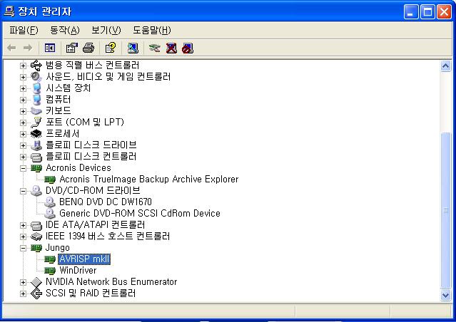
3.아뒤노와 usbisp를 컴퓨터에 연결한다. usbisp 드라이버는
C:\Program Files\Atmel\AVR Tools\usb 에 있다.
장치 관리자에서 아래와 같이 보여진다면 제대로 설치가 된것이다.
4. 기존의 아뒤노 보드의 ATmega8 또는 168을 제거하고 새 ATmega8 또는 168를 꼽아준다.
5. AVR Studio를 실행한다.
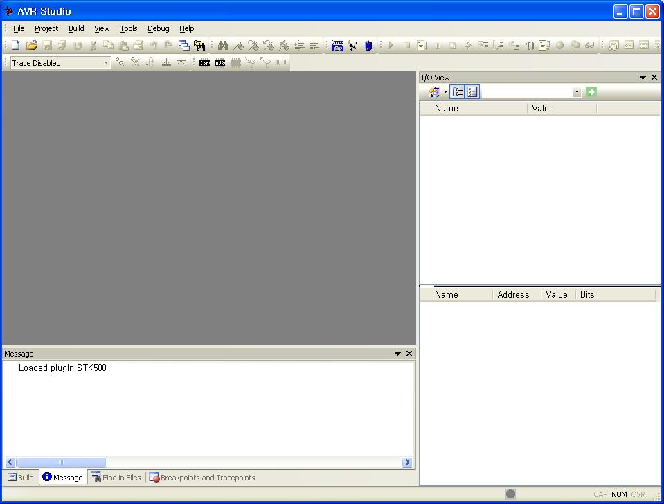
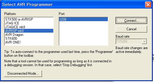
6.Arduino ICSP에 USBISP를 연결한다. 케이블에서 빨간색부분이 1번 부분이다.
7.그림과 같이 따라한다. 클릭 클릭
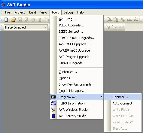
8.
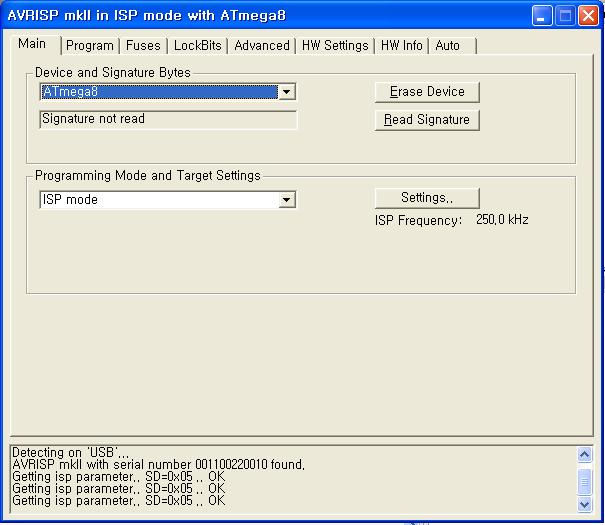
9.메인 탭에서 Device and Signature Bytes에서 ATmega8을 선택한후 Erase Device를 누른다.
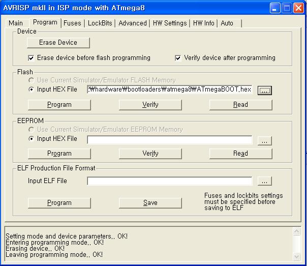
10.Program 메뉴에서 Erase Device를 누르고, Flash에서 HEX파일의 저장경로를 찾아준다
아뒤노폴더에 보면 arduino-0012\hardware\bootloaders 에 각각 칩에 해당하는 HEX파일이 있다.
그리고 Program버튼을 누른다.
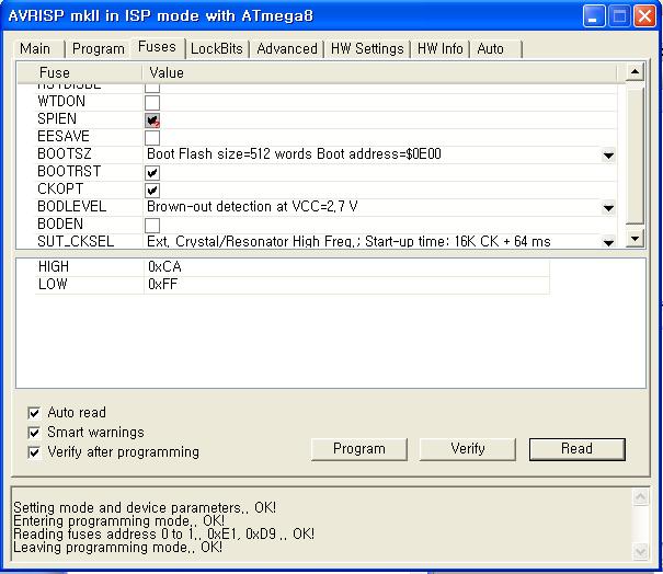
11.Fuse탭에서 아래와 같이 설정하고 Program을 누른다.(아래는 ATmega 8 셋팅)
ATmega8 Fuse Settings
Once set the fuses should read 0xCA and 0xFF, which is equivalent to:
- Boot Flash section size = 512 words Boot start address = $0E00; [BOOTSZ=01]
- Boot Reset Vector Enabled (default address = $0000); [BOOTRST=0]
- CKOPT fuse (operation dependant of CKSEL fuses); [CKOPT=0]
- Brown-out detection level at VCC=2.7V; [BODLEVEL=1]
- Ext. Crystal/Resonator High Freq.; Start-up time: 16K CK + 64ms; [CKSEL=1111 SUT=01]
ATmega168 Fuse Settings
Once set the fuses should read 0xF8, 0xDF and 0xFF, which is equivalent to:
- Boot Flash section size = 1024 words Boot start address = $1C00; [BOOTSZ=00]; default value
- Boot Reset Vector Enabled (default address = $0000); [BOOTRST=0]
- Brown-out detection disabled; [BODLEVEL=111]
- Ext. Crystal Osc.; Frequency 8.0 - MHz; Startup time PWRDWN/RESET: 16K CK/14 CK + 64ms; [CKSEL=1111 SUT=0]
12.LockBits 탭에서 아래와 같이 설정하고 Program한다.
Once set the lockbits should read 0xFF for ATmega8 and 0xCF for ATmega168, which is equivalent to:
- Mode1: No memory lock features enabled
- Application Protection Mode1: No lock on SPM and LPM in Application Section
- Boot Loader Protection Mode3: LPM and SPM prohibited in Boot Loader Section

아뒤노 프로그램에서 잘 되는지 확인해 본다.
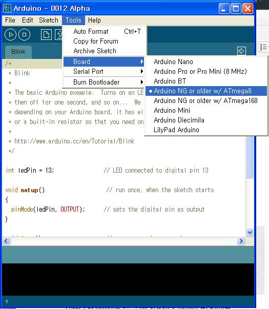
<주의> 현재 아뒤노 보드는 Diecimila버전인데 이 버전엔 ATmega168이 사용되었다. 이 버전에 ATmega8을 사용하고자 할때는 아래와 같이 보드 셋팅을 바꿔줘야 한다.
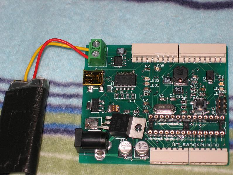
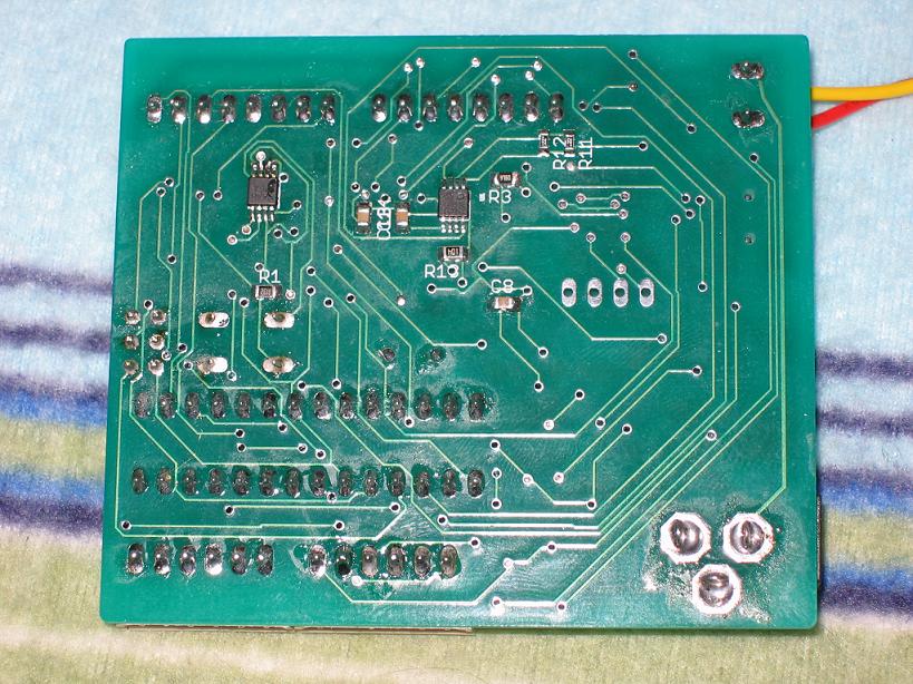
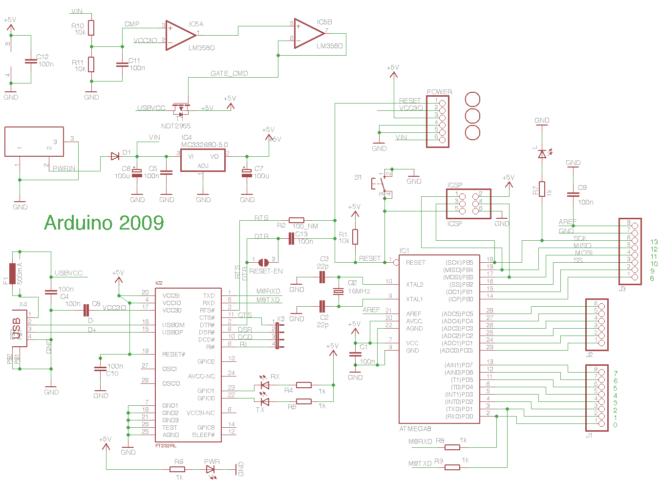
이번에 제작하게된 커스텀 안_상큼이노.ㅡㅡㅋ
리튬폴리머 전지로 작동하게 되며 외부전원신 충전이 된다.
기존 아뒤노 보드에 리튬폴리머 충전회로와 드라이빙회로가 추가되었다.
이래나 저래나 작동은 한다.ㅋㅋ 관람포인트는 전부 수땜
- Summary datasheet pdf, 33 pages.
- Complete datasheet pdf, 374 pages.
R(저항) = V(인가전압-LED정격전압) / If(LED의 소비전류) 입니다.
입력 5V 에 LED는 3.3V 20mA 라면 (5 - 3.3) / 0.02 = 85옴
 Sparkfun now sells a variation of the Arduino called the "Arduino Pro".
Check out the specifications to see if it's the right board for your
next project. If you are new to micro-controllers, I would start with
an Arduino Diecimila since the Pro needs a few thing to get it connected. The Arduino Pro is BYOC, that's "bring your own connectors".
Sparkfun now sells a variation of the Arduino called the "Arduino Pro".
Check out the specifications to see if it's the right board for your
next project. If you are new to micro-controllers, I would start with
an Arduino Diecimila since the Pro needs a few thing to get it connected. The Arduino Pro is BYOC, that's "bring your own connectors".
It's blue! It's skinny! It's the Arduino Pro! SparkFun's minimal design approach to Arduino. This is a 3.3V Arduino running the 8MHz bootloader (select 'LilyPad' within the Arduino software). The Arduino Pro is very much like the Skinny, but we added a handful of features to become a fully certified Arduino board. The power switch was moved to the side of the board (good idea Limor!) to allow control when a shield is attached.
More about the Arduino Pro


